Step-By-Step Creation of FMS 2 Alpha 8 .par Files
by Gary Gunnerson, Feb 6th, 2004
FMS Home
Page
FMS
Forum
www.rc-sim.de Forum
RC Groups
Sim Forum
Other FMS Links
Note: November 2012, this par file creation discussion is a bit obsolete. Once Mr. Masuoka created his awesome FMS 2 alpha 8 .par file editor, the amount of work required to create a good FMS alpha 8 .par was much reduced.
The only thing that changed between FMS 2 beta7 and alpha8 was the .par file. All
other items including the sound .wav file, the model .x file, the preview .jpg
and image map .bmp file all remain the same. The .par file for FMS alpha8 is
extremely different from the prior version of FMS. It has been significantly
expanded to include a lot more data to more accurately simulate actual model
flight characteristics. The beta7 .par included the following items:
- Type(-)
Type[0=Plane]
- Tmax(N) Maximum Thrust, now computed by MOTOR data
- Drmax(rad) Maximun Rudder Angle, in surface (Fläche) number 4
- Demax(rad) Maxmim Elevator Angle, in surface (Fläche) number 3
- Damax(rad) Maximim Aileron Angle, in surface (Fläche) numbers 1&2
- CLmax(-) Maximum Lift Coefficient, in POLAR data
- CLmin(-) Minimum Lift Coefficient, in POLAR data
- CLa(/rad) Lift Gradient, in POLAR data
- CLaSt(/rad) Lift Gradient in Stall, in POLAR data
- CDw(-) Drag Coefficient of Wing, in POLAR data + DRAG data
- CDb(-) Drag Coefficient of Fuselage, in POLAR data + DRAG data
- mug(-) Friction Coefficient of Wheels, in WHEEL data
- dCDSt(-) Rise of Drag Coefficient in Stall, in POLAR data
- CM(-) Moment Coefficient, in POLAR data
- alpha0(rad) Wing Angle, in surface (Fläche) numbers 1&2, 7&8 (biplane)
- b(m) Wing Span, in surface (Fläche) numbers 1&2, each ½ total span
- c(m) Wing Chord, in each surface (Fläche)
- hce(m) Equivalent Center of Gravity, in MAIN, now X,Y,Z coordinate
- m(Kg) Mass, in MAIN
- Izz(Kg*m^2) Yaw Inertia Moment, in MAIN
- Iyy(Kg*m^2) Pitch Inertia Moment, in MAIN
- Ixx(Kg*m^2) Roll Inertia Moment, in MAIN
- She(m^2) Effective Area of Stab, calculated from surface (Fläche) 3 data
- Sfe(m^2)
Effective Area of fin, calculated from surface (Fläche) 4 data
- Lt(m) Tail Moment Arm, calculated from position of surface (Fläche) 4 data
- VForm(-) Effect of Dihedral Angle, calculated by vectors (ex, ey) for each surface (Fläche).
To create a new .par file youll need to gather information for the actual model youre trying to simulate.
1) Youll need the actual
weight of the model in kilograms and the actual span of your model in meters. Its
easy enough to convert numbers using Google by typing in a search like convert
36 inches to meters. Youll get the result that 36 inches =
0.9144 meters. Or
you could put in the query to convert 16 ounces to kilograms and get the
result that 16 ounces = 0.45359237 kilograms.
2) Next youll need the current
and accurate Metasequoia LE .mqo 3D model file for the model well be using to
create the new .par file. This must be an accurate model rendering with an
accurate center of gravity. If this file is not accurate, your virtual model
will not fly correctly.
3) You should have a copy of my mqo-browser program to convert .mqo coordinate data to FMS .par coordinates. It would also be useful to have my Excel spreadsheet for calculating ex and ey surface coordinates representing sweep or dihedral. Both are available at: my website.
Modify the 3D Model
Well start first by modifying the Metasequoia model to supply the needed data for each surface (Fläche) required by the new .par file. The goal of this exercise is to end up with a left wing and right wing as separate objects, have an elevator that is full length, have a rudder that is a different object than the fuselage and have accurate positions for the center of gravity (CG) and wheel locations. As our example, well use the Fkstick.mqo file located at the http://rc-sim.de download area.
 |
This models objects and materials are written in Japanese. Dont worry though; well change the names of the objects to make it easier for English readers. | |
| The easiest way to identify which objects correspond to model components is to click on and off the eye icon until you identify the actual object. This object is the wing. Well now want to change the name of the object to wing. Just double click on the object name and a dialog box will open up allowing you to type in the new name. |  |
|
 |
The wing is a left wing only with 3D mirroring as indicated by mirroring section of the object property dialog box. If this had been a full width wing, wed need to split the wing into left and right wing objects by using cut and paste. The alpha8 .par requires separate left and right wing surfaces for surface 1 and 2. | |
Since the new alpha8 .par file wants a unique surface for each airplane object, we now need to at least change the name of the five surface objects required in our 3D file. I use wing, elevator, rudder and fuselage as the object names for these model parts. Ill also discover and name the wheel and the propeller objects as they are required for locating the WHEEL and MOTOR elements in the FMS alpha8 .par file.
 |
As you click on the elevator object, youll note that it is half width and not full width as required by the new .par file. In order to make the elevator full width, you need to turn off mirroring by selecting None in the mirroring section of the Object Property dialog box. Just double click on the objects name to see the dialog box. | |
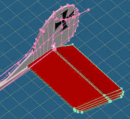
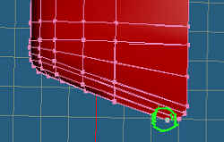
| Then unclick the lock button next to the object and use the Edit Sel Obj button to select the elevator. The lines and dots will turn green when selected like this picture |  |
|
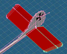 |
After youve selected the elevator object, then use the Selected, Mirror, YZ command from the main menu to create the other half of the elevator. Your elevator will now look like this. We did this in order to easily measure the full width of the elevator for the .par file. The surface location, width and span would be wrong if the elevator was not full width. | |
| One last check to make is where the center of gravity (CG) for the entire 3D model is located within Metasequoia. The best way to check this is by viewing the model in a side view by touching the keyboards <F1> key. FMS 2 alpha8 uses a center point for all surfaces that is 25% back from the leading edge. A good CG for your model would be the same 25% of the chord back from the leading edge unless your model flies with a different CG. The best CG to use is the actual CG of the model. Remember though that the FMS CG is the center of mass for the model too and it may need to be moved upward or downward. To move the model around the CG you uncheck all the key icons for all objects, click the Sel All button and use the Edit Panel move buttons to adjust the models position relative to the proper center of gravity. | 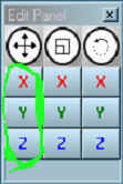 |
Determine your models collision points
At this point its a good time to save your model. I saved my modified model to FKstick8.mqo and Fkstick8.x. If youre working along in the tutorial, use a different name. Before we leave Metasequoia, well want to locate and record collision points and wheel locations for the .par file. This is pretty straight forward but should only be done after saving the file as you do not want to possibly mess up your model during the collision and wheel location exercise.
 |
To find out the location of your collision points, youll need to take a look at your model from the side <F1> and top <F2> to get an idea which positions seem like good collision points. The nose tip, both wing tips and top of the tail are minimum collision points. To figure out the collision point, unclick the key icon on the object you want to measure, on the Command menu click the Select button, then click on a single pixel representing a collision point. |
| In order to derive the actual collision point of the wing object you then click on the Move button in the Command menu and select the Abs button on the dialog box. Now comes the tricky part. The actual .par file coordinate of this collision point for the left wing is X = -.1291, Y = -.8534 and Z = -.1383. Your model may be different if you adjusted your CG earlier. Converting Metasequoia to FMS coordinates requires X to be Z, Y to be X and Z to be Y while dividing each coordinate by 100 or sliding the decimal place 2 points to the left. The right wing collision point is the same as the left wing but with a positive Y coordinate i.e. .1291 .8534 -.1383. | 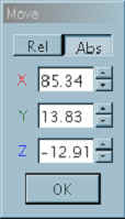 |
For the FKstick model, I also chose the top and bottom of the prop as collision points along with a point on the top of the tail. For determining wheel position for the WHEEL section of the .par file, I clicked on points at the bottom of the wheel and the tip of the tail skid. If youve followed along to this point youll now have 5 collision points and 3 wheel positions that you need to write down on a piece of paper.
Running mqo-browser.exe
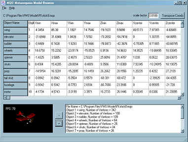 |
Next we run the mqo-browser.exe helper application to calculate the appropriate wing position points, chord and span for each of the 5 (or 7 for biplanes) model surfaces. After clicking on the mqo-browser.exe file, select <File> <Open-MQO> to load a Metasequoia model file. Well load fkstick8.mqo into the program to see a screen like this. It will have the raw data from the .mqo file. |
At this point we want to transpose the coordinates from .mqo to FMS and we do that by adjusting the scale factor and clicking the <Transpose Coords> button. The scaling factor adjusts the models surfaces to be equal to the actual model. A scale factor of 0.0100 slides the decimal 2 places to the right making 1 unit equal .01 meter or 100 units equal one meter.
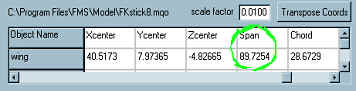 |
With the FKstick model, the actual wingspan of a SlowStick is 1.2 meters or .6 meters per wing. Since the current span is 89.7254, we need to make the scale factor smaller or set it at 0.0067. The easiest way to calculate your models scale factor is to divide your actual one-sided wing span by the .mqo files current span number. |
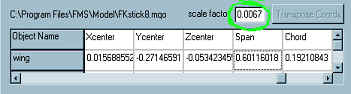 |
In our case .60 meter divided by .897254 or .6687 or .67 with rounding. Youll see that the span is now close to .6m as desired. |
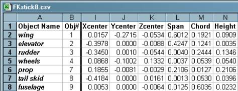
At this point, I save my data as a CSV file and use Excel to print it out. The 5 surfaces youll have center points span and chord for are left wing, right wing (derived from left wing), elevator, rudder and fuselage. From my FKstick.csv file I have the following points defined.
Edit Your Models .par File
Its easiest to start with an existing file and edit the contents. Remember that the .par file contains information from the original .mqo model file which translates directly to the .x file, such as wheel points, collision points and height above ground. The .par file also contains information from the FKstick8.csv to more appropriately calculate actual wing parameters for motor position, wing position, spans and chords. And lastly, the .par file holds information derived from other models for MOTOR data like prop pitch, length and chord, motor power and fuel/battery consumption. Electric motors use 1.2 volts per cell. Without more exploring, we just modify this data by trial and error until the model flies right.
First fill out the VERSION, INFO, MODELTYPE and MAIN
sections at the beginning of the .par file.
Start of .par file
VERSION 1.0
INFO //Free Form Comment Area, does not change model
Name:FK Stick (Stick type Fokker Eindecker) //Plane Name
SlowFlyer //Type of Plane
Spannweite: 1.2 m //Span (m)
Gewicht: .4 kg //Weight (kg)
Motorisierung: GWS 300C //Engine
Prop: 10x4.7 //Prop
Akku: 8 cell //Battery (7 Zellen = 7 cells)
Kapazität des Akkus: 750mAh //Battery Capacity
RC-Funktionen: //RC Functions
Kanal 1: Rudder //Channel 1 (Seitenruder = rudder, Heckrad = tail wheel)
Kanal 2: Elevator //Channel 2 (Höhenruder = elevator)
//Channel 3 (Querruder = Aileron)
Kanal 4: Motor //Channel 4 (Motordrossel = Engine Throttle)
Copyright Author:Shinichiro_Nishiya
E-mail:nishiya@actv.ne.jp
Homepage:http://www.hoops.ne.jp/%7Ekimagure-hikoki/index_e.html
New FMS alpha8.1 .par file by Gary Gunnerson http://gunnerson.homestead.com/files/fms_models.htm
ENDINFO //ENDINFO, end comment area
AIRPLANE //Flächenmodell (Surface Model)
MAIN //allgemeine Daten (General Data), copied from Transall when unknown
0.4   //Masse des Modells [kg] (Model Mass, from actual model)
0.11  //Trägheitsmoment um die Querachse (Ixx) [kg*m^2]
      //(moment of inertia around x-axis)
0.2   //Trägheitsmoment um die Längsachse (Iyy) [kg*m^2]
      //(moment of inertia around y axis)
0.5   //Trägheitsmoment um die Hochachse (Izz) [kg*m^2]
      //(moment of inertia around z axis)
-0.06 //Deviationsmoment (Ixz) [kg*m^2] (product of inertia)
0 0 0 //Position des Schwerpunktes [m]
      //(position of the center of gravity, adjust if power off glide is poor)
0.22  //Flugzeughöhe (0-Punkt über Boden - für Initialisieren) [m]
      //(airplane height over ground, actual .mqo lowest wheel + .01 meter)
Motor:
MOTOR //Motor(en) (motor, engine, position from FKstick, others, adjust as required)
0.1855 -0.0081 -0.0029 //Position [m] (position, from FKstick.csv, propeller)
1 0 0 //Zugrichtung (direction of thrust)
0.30  //Propellerdurchmesser [m] (prop diameter, close to real prop)
0.14  //Pitch, Steigung des Propellers [m] (pitch, upward gradient of prop)
2     //Anzahl Propellerblätter (number of prop blades)
0.015 //mittlere Propellerblatttiefe [m] (mean chord length of prop blades)
RIGHT //rechtsdrehender Propeller (clockwise rotating prop)
0.02  //Rotationsträgheitsmoment von Propeller und Motor [kg*m^2]
      //(rotation moment of inertia)
4     //Kanal (channel 4)
ELECTRO //Motortyp = Verbrennungsmotor (motor type = COMBUSTION/ELECTRO)
7.2   //Nennspannung des Motors [V] (motor voltage, should be multiple of 1.2 volts)
8000  //Leerlaufdrehzahl [U (idling speed)
1     //Leerlaufstrom [A] (idling current)
10    //Blockierstrom [A] (blocking current)
1     //Übersetzung des Getriebes (typischerweise > 1) [-]
      //(translation of transmission, typical > 1)
1     //Getriebewirkungsgrad [-] (transmission efficiency)
8     //Anzahl Zellen des Akkus (jeder Motor hat seinen eigenen Akku) [-]
      //(number of batt cells at 1.2 volts per cell, increase for more voltage)
750   //Kapazität des Akkus (0=Akku nie leer) [mAh] (batt capacity, 0 = never empty)
5     //Innenwiderstand des Akkus [mOhm] (internal battery resistance)
Wings:
WING //Flächen (surfaces, left and right wing)
//Fläche Nr. 1 Surface number 1, left wing, if aileron then channel 3
0.0157 -0.2715 -0.0534 //Position [m] (position, from FKstick8.csv)
1 0 0           //ex (unit vector in flight direction - 6 degree dihedral)
0 0.9945 0.1045 //ey (unit vector in direction of wing span)
1      //Polare (Nr.) (polar number used below, usually Polar 1)
0.6012 //Flächenbreite (Spannweite) [m] (surface width - span, from FKstick.csv)
4      //Anzahl Elemente (number of elements, default for AUTOELEMENT)
AUTOELEMENT //Alle Elemente sind gleich gross (all elements have equal size)
1.0    //Anstellwinkel [°] (angle of attack, actual model)
0.1921 //Flächentiefe Anfang [m] (chord length at the first end, from FKstick.csv)
0.1921 //Flächentiefe Ende [m] (chord length at the second end, from FKstick.csv)
0      //Klappentiefe [m] (chord length of the flap, no aileron)
0      //Klappenanfang [m (start position of the flap, no aileron)
0      //Klappenende [m] (end position of the flap, no aileron)
0      //maximaler Ausschlag [°](maximum flap deflection, no aileron)
0      //Kanal (channel, no control required)
//Fläche Nr. 2 Surface number 2, right wing, if aileron then channel 3
0.0157 0.2715 -0.0534 //Position [m] (position, from FKstick, opposite Y coord)
1 0 0            //ex (unit vector in flight direction - 6 degree dihedral)
0 0.9945 -0.1045 //ey (unit vector in direction of wing span)
                 //(all other lines the same as surface 1)
Elevator:
//Fläche Nr. 3 Surface number 3, elevator, channel 2
-0.3978 0 -0.0088 //Position [m] (position, from FKstick.csv)
1 0 0  //ex (unit vector in flight direction, no sweep, no dihedral)
0 1 0  //ey (unit vector in direction of wing span)
2      //Polare (Nr.) (polar number used below, usually 2)
0.4247 //Flächenbreite (Spannweite) [m] (surface width - span, from FKstick.csv)
4      //Anzahl Elemente (number of elements, default for AUTOELEMENT)
AUTOELEMENT //Alle Elemente sind gleich gross (all elements have equal size)
-1     //Anstellwinkel [°] (angle of attack works with wing AofA)
0.1241 //Flächentiefe Anfang [m] (chord length at the first end, from FKstick.csv)
0.1241 //Flächentiefe Ende [m] (chord length at the second end, fixed width elevator)
0.04   //Klappentiefe [m] (chord length of the flap, control width)
0      //Klappenanfang [m] (start position of the flap, full width flap = zero to span)
0.4247 //Klappenende [m] (end position of the flap)
10     //maximaler Ausschlag [°] (maximum flap deflection)
1      //Kanal (channel)
Rudder:
//Fläche Nr. 4 Surface number 4, rudder, channel 1
-0.3450 0.0010 -0.0544 //Position [m] (position, from FKstick.csv)
0.93969 0 -0.34202     //ex (unit vector in flight direction, 20.47 degree sweep)
-0.34202 0 -0.93969    //ey (unit vector in direction of wing span)
2      //Polare (Nr.) (polar number used below, usually 2)
0.26   //Flächenbreite (Spannweite) [m] (surface width - span = height (Z) for rudder,)
       //usually double this for better rudder authority, your choice
4      //Anzahl Elemente (number of elements, default for AUTOELEMENT)
AUTOELEMENT //Alle Elemente sind gleich gross (all elements have equal size)
0      //Anstellwinkel [°] (angle of attack)
0.3444 //Flächentiefe Anfang [m] (chord length at the first end, added .1 m from FKstick)
0.3444 //Flächentiefe Ende [m] (chord length at the second end)
0.17   //Klappentiefe [m] (chord length of the flap, half of chord)
0      //Klappenanfang [m] (start position of the flap)
0.26   //Klappenende [m] (end position of the flap, chord = full width)
-30    //maximaler Ausschlag [°] (maximum flap deflection)
2      //Kanal (channel, use channel 1 for left stick rudder, 3 for single stick xmtr.)
Fuselage & Drag:
//Fläche Nr. 5 Surface number 5, fuselage or body, channel 0
0.0053 0 -0.0064 //Position [m] (position, from FKstick.csv)
1 0 0  //ex (unit vector in flight direction
0 0 -1 //ey (unit vector in direction of wing span)
3      //Polare (Nr.) (polar number used below, usually 3)
0.0125 //Flächenbreite (Spannweite) [m] (surface width - span, from FKstick.csv)
3      //Anzahl Elemente (number of elements, default for AUTOELEMENT)
AUTOELEMENT //Alle Elemente sind gleich gross (all elements have equal size)
0 //Anstellwinkel [°] (angle of attack)
0.6035 //Flächentiefe Anfang [m] (chord length at the first end, from FKstick.csv)
0.6035 //Flächentiefe Ende [m] (chord length at the second end, length of fuse)
0      //Klappentiefe [m] (chord length of the flap)
0      //Klappenanfang] (start position of the flap)
0      //Klappenendm] (end position of the flap)
0      //maximaler Ausschlag [°] (maximum flap deflection)
0      //Kanal (channel)
DRAG
0.0053 0 -0.0064 //Position [m] (position - used fuselage position from FKstick.csv)
0.009  //Referenzfläche [m^2] (reference cross section)
0.01   //cw (drag coefficient, increase if too fast)
0      //Kanal (0=kein) (channel)
Polar:
The POLAR files are taken from existing models that closely approximate your model. I've modified these a bit but have not seen the kind of results that are worth sharing at this point. If someone else has experience here, please share it with us.
Collision Points:
Are closely related to wheel positions which are also collision points. These points represent where on the model and how a crash is registered. Prior versions of FMS only used the center of gravity. I use the actual Metasequoia points recorded earlier for these positions not adjusted for any factor. Here we have the 5 collision points we discussed, top of prop, bottom of prop, left wingtip, right wingtip and the high point of the rudder.
POINT //Gleitpunkte (collision points)
0.2725 0 -0.1615 //Position [m] (position, top of prop)
1200 //Federkonstante [N/m] (spring constant)
35   //Dämpfung [N*s/m] (damping)
50   //Bruchkraft [N] (breaking load)
1.2  //Reibungskoeffizient [-] (coefficent of friction)

0.2725 0 0.1615 //Position [m] (position, bottom of prop)
1200 //Federkonstante [N/m] (spring constant)
35   //Dämpfung [N*s/m] (damping)
80   //Bruchkraft [N] (breaking load)
1.2  //Reibungskoeffizient [-] (coefficent of friction)

-0.1561 -0.8534 -0.1383 //Position [m] (position, left wingtip)
1200 //Federkonstante [N/m] (spring constant)
35   //Dämpfung [N*s/m] (damping)
80   //Bruchkraft [N] (breaking load)
1.2  //Reibungskoeffizient [-] (coefficent of friction)

-0.1561 0.8534 -0.1383 //Position [m] (position, right wingtip)
1200 //Federkonstante [N/m] (spring constant)
35   //Dämpfung [N*s/m] (damping)
80   //Bruchkraft [N] (breaking load)
1.2  //Reibungskoeffizient [-] (coefficent of friction)

-0.7098 0 -0.1808 //Position [m] (position, rudder high point)
1200 //Federkonstante [N/m] (spring constant)
35   //Dämpfung [N*s/m] (damping)
80   //Bruchkraft [N] (breaking load)
1.2  //Reibungskoeffizient [-] (coefficent of friction)
Wheels:
Wheels are used to steer the model on the ground and as collision points if you hit to hard during a landing. I've found that I need to move the wheels outward from the center of gravity to have a better taxi experience. For this model I took the front wheel coordinate from the 3D model and added .05 meter to the Y coordinate. The Z coordinate for the wheel is very critical, too low and the model will sink into the ground and too high and it will float above. The 3D model point was .2392 meters, I used .24. If the model bounces around, decrease the spring constant. Increasing the friction coefficient in the trace direction will inhibit the wheel turning in the forward direction. Decreasing the friction coefficient in the transverse direction will cause the model to slide more during turns.
WHEEL //Fahrwerkspunkte (Räder) (points of chassis - wheels)
0.1 -0.2 0.24 //Position [m] (position front left wheel, close to .mqo collision point)
1000 //Federkonstante [N/m] (spring constant)
20   //Dämpfung [N*s/m] (damping, increase if too much wobble)
80   //Bruchkraft [N] (breaking load, when collision happens)
0 -1 0 //Achsvektor (axis vector)
0.18 //Reibungskoeffizient in Spurrichtung [-]
     //(coefficient of friction trace direction)
0.6  //Reibungskoeffizient quer zur Spurrichtung [-] \
     //(coeff. of fric. transverse direction)
0    //Kanal (channel, used for wheel that steers)
0    //maximaler Ausschlag [°] (maximum deflection of the wheel when steering)

0.1 0.2 0.24 //Position [m] (position front right wheel, mirror of left wheel on +Y coord)
1000 //Federkonstante [N/m] (spring constant)
20   //Dämpfung [N*s/m] (damping)
80   //Bruchkraft [N] (breaking load)
0 1 0 //Achsvektor (axis vector)
0.18 //Reibungskoeffizient in Spurrichtung [-]
     // (coefficient of friction trace direction)
0.7  //Reibungskoeffizient quer zur Spurrichtung [-]
     //(coeff. of fric. transverse direction)
0    //Kanal (channel, used for wheel that steers)
0    //maximaler Ausschlag [°] (maximum deflection of the wheel when steering)

-0.6811 0 0.06 //Position [m] (position rear tail wheel, close to .mqo file)
1200 //Federkonstante [N/m] (spring constant)
20   //Dämpfung [N*s/m] (damping)
80   //Bruchkraft [N] (breaking load)
0 1 0 //Achsvektor (axis vector)
0.18 //Reibungskoeffizient in Spurrichtung [-]
     //(coefficient of friction trace direction)
0.8  //Reibungskoeffizient quer zur Spurrichtung [-]
     //(coeff. of fric. transverse direction)
3    //Kanal (channel, use 1 for left stick)
-20  //maximaler Ausschlag [°] (maximum deflection of the wheel when steering)
This concludes the tutorial on creating a new FMS 2 alpha8 .par file for an existing FMS beta7 model. I've used this method several times now and it seems to produce repeatable results as long as the Metasequoia LE 3D model file is accurate. If you find any errors in this tutorial, please email an update request at the address below.
![]()
![]()
![]()